SAME SIGNALS. DIFFERENT BOARD SIZES.
Zero or full-size Pi?
The header matches.
Pi Zero family
Pi Zero, Zero W, Zero WH and Zero 2 W use the same standard 40-pin signal layout. Many Zero boards arrive with bare holes: use a properly soldered 2 × 20, 2.54 mm header or a pre-soldered version.
Pi 3, Pi 4 & Pi 5
These full-size boards use the same 40-pin layout shown below. Pi 400 also uses that signal layout, but its connector faces differently — check the model’s pin-1 marking before attaching a cable.
The original Pi Zero and Zero W have this pinout but do not support the current Chromium kiosk setup. Use a Pi Zero 2 W or newer for ORBPuzzles’ Pi kiosk. This map does not cover early 26-pin Model A/B boards, Raspberry Pi Pico, or bare Compute Modules.
Pin functions and enabled peripherals vary by model and configuration. A green pin here is a candidate, not proof it is free on your Pi. HATs, overlays and another application can claim any GPIO.
Two numbers. One actual pin.
Physical pin is the connector position, from 1 to 40. BCM / GPIO number identifies the signal used by ORBPuzzles and GPIO Zero.
Enter 17, not 11, in Admin > GPIO for this example. Power and ground positions do not have BCM input numbers.
The whole header.
At a glance.
View from the component / connector side, not the underside. This diagram is rotated to put physical pin 1 at the upper left; rotate your view to match your board’s pin-1 mark. A square solder pad often identifies pin 1 — confirm with your model’s documentation. Don’t rely on the HDMI or USB connector position.
- Input / output candidate
- GPIO / check shared function
- 3.3 V power / not an input
- 5 V power / not an input
- Ground / not an input
- HAT ID / leave unused
| ODD PHYSICAL PINS | EVEN PHYSICAL PINS |
|---|---|
|
3.3 V3.3 V power / not an inputNOT A GPIO INPUT
1
|
5 V5 V power / not an inputNOT A GPIO INPUT
2
|
|
BCM 2I2C SDACHECK FUNCTION
3
|
5 V5 V power / not an inputNOT A GPIO INPUT
4
|
|
BCM 3I2C SCLCHECK FUNCTION
5
|
GNDGround / not an inputNOT A GPIO INPUT
6
|
|
BCM 41-Wire / clockCHECK FUNCTION
7
|
BCM 14UART TXCHECK FUNCTION
8
|
|
GNDGround / not an inputNOT A GPIO INPUT
9
|
BCM 15UART RXCHECK FUNCTION
10
|
|
BCM 17General GPIOINPUT / OUTPUT
11
|
BCM 18PWM / PCM clockCHECK FUNCTION
12
|
|
BCM 27General GPIOINPUT / OUTPUT
13
|
GNDGround / not an inputNOT A GPIO INPUT
14
|
|
BCM 22General GPIOINPUT / OUTPUT
15
|
BCM 23General GPIOINPUT / OUTPUT
16
|
|
3.3 V3.3 V power / not an inputNOT A GPIO INPUT
17
|
BCM 24General GPIOINPUT / OUTPUT
18
|
|
BCM 10SPI MOSICHECK FUNCTION
19
|
GNDGround / not an inputNOT A GPIO INPUT
20
|
|
BCM 9SPI MISOCHECK FUNCTION
21
|
BCM 25General GPIOINPUT / OUTPUT
22
|
|
BCM 11SPI clockCHECK FUNCTION
23
|
BCM 8SPI CE0CHECK FUNCTION
24
|
|
GNDGround / not an inputNOT A GPIO INPUT
25
|
BCM 7SPI CE1CHECK FUNCTION
26
|
|
BCM 0ID_SDLEAVE UNUSED
27
|
BCM 1ID_SCLEAVE UNUSED
28
|
|
BCM 5General GPIOINPUT / OUTPUT
29
|
GNDGround / not an inputNOT A GPIO INPUT
30
|
|
BCM 6General GPIOINPUT / OUTPUT
31
|
BCM 12PWMCHECK FUNCTION
32
|
|
BCM 13PWMCHECK FUNCTION
33
|
GNDGround / not an inputNOT A GPIO INPUT
34
|
|
BCM 19PCM / SPI1CHECK FUNCTION
35
|
BCM 16General GPIOINPUT / OUTPUT
36
|
|
BCM 26General GPIOINPUT / OUTPUT
37
|
BCM 20PCM / SPI1CHECK FUNCTION
38
|
|
GNDGround / not an inputNOT A GPIO INPUT
39
|
BCM 21PCM / SPI1CHECK FUNCTION
40
|
Full reference: functions and notes for all 40 pins
| Physical | BCM | Type | Function / note |
|---|---|---|---|
| 1 | — | 3.3 V power / not an input | 3.3 V Regulated power rail; not a GPIO signal. |
| 2 | — | 5 V power / not an input | 5 V Power rail; never connect to a GPIO input. |
| 3 | 2 | GPIO / check shared function | I2C SDA I2C data with a fixed board pull-up; avoid for beginner button wiring. |
| 4 | — | 5 V power / not an input | 5 V Power rail; never connect to a GPIO input. |
| 5 | 3 | GPIO / check shared function | I2C SCL I2C clock with a fixed board pull-up; avoid for beginner button wiring. |
| 6 | — | Ground / not an input | GND Ground; a convenient return for the example button. |
| 7 | 4 | GPIO / check shared function | 1-Wire / clock Often used by the 1-Wire overlay or a clock output; check first. |
| 8 | 14 | GPIO / check shared function | UART TX Serial transmit; do not repurpose while a serial console or device uses it. |
| 9 | — | Ground / not an input | GND Ground; electrically common with the other ground pins. |
| 10 | 15 | GPIO / check shared function | UART RX Serial receive; do not repurpose while a serial console or device uses it. |
| 11 | 17 | Input / output candidate | General GPIO Suggested first button input, if unclaimed. |
| 12 | 18 | GPIO / check shared function | PWM / PCM clock Common audio/PWM conflict; avoid until the pin is confirmed free. |
| 13 | 27 | Input / output candidate | General GPIO Input or output candidate, if unclaimed; never use for both at once. |
| 14 | — | Ground / not an input | GND Ground; electrically common with the other ground pins. |
| 15 | 22 | Input / output candidate | General GPIO Suggested button input, if unclaimed. |
| 16 | 23 | Input / output candidate | General GPIO Suggested button input, if unclaimed. |
| 17 | — | 3.3 V power / not an input | 3.3 V Regulated power rail; not a GPIO signal. |
| 18 | 24 | Input / output candidate | General GPIO Suggested button input, if unclaimed. |
| 19 | 10 | GPIO / check shared function | SPI MOSI SPI0 data out; available as GPIO only when not claimed by SPI or another function. |
| 20 | — | Ground / not an input | GND Ground; electrically common with the other ground pins. |
| 21 | 9 | GPIO / check shared function | SPI MISO SPI0 data in; available as GPIO only when not claimed by SPI or another function. |
| 22 | 25 | Input / output candidate | General GPIO Suggested button input, if unclaimed. |
| 23 | 11 | GPIO / check shared function | SPI clock SPI0 clock; available as GPIO only when not claimed by SPI or another function. |
| 24 | 8 | GPIO / check shared function | SPI CE0 SPI0 chip select; check attached devices and enabled SPI first. |
| 25 | — | Ground / not an input | GND Ground; electrically common with the other ground pins. |
| 26 | 7 | GPIO / check shared function | SPI CE1 SPI0 chip select; check attached devices and enabled SPI first. |
| 27 | 0 | HAT ID / leave unused | ID_SD Reserved for HAT EEPROM identification; leave unused for room inputs. |
| 28 | 1 | HAT ID / leave unused | ID_SC Reserved for HAT EEPROM identification; leave unused for room inputs. |
| 29 | 5 | Input / output candidate | General GPIO Additional input/output candidate, if unclaimed. |
| 30 | — | Ground / not an input | GND Ground; electrically common with the other ground pins. |
| 31 | 6 | Input / output candidate | General GPIO Additional input/output candidate, if unclaimed. |
| 32 | 12 | GPIO / check shared function | PWM Check PWM, audio and peripheral overlays before assigning as GPIO. |
| 33 | 13 | GPIO / check shared function | PWM Check PWM, audio and peripheral overlays before assigning as GPIO. |
| 34 | — | Ground / not an input | GND Ground; electrically common with the other ground pins. |
| 35 | 19 | GPIO / check shared function | PCM / SPI1 Check digital audio, SPI1 and other overlays before assigning as GPIO. |
| 36 | 16 | Input / output candidate | General GPIO Additional input/output candidate, if unclaimed. |
| 37 | 26 | Input / output candidate | General GPIO Additional input/output candidate, if unclaimed. |
| 38 | 20 | GPIO / check shared function | PCM / SPI1 Check digital audio, SPI1 and other overlays before assigning as GPIO. |
| 39 | — | Ground / not an input | GND Ground; electrically common with the other ground pins. |
| 40 | 21 | GPIO / check shared function | PCM / SPI1 Check digital audio, SPI1 and other overlays before assigning as GPIO. |
Start with these inputs.
For simple normally-open buttons or isolated dry-contact puzzle switches, these are good starting candidates. They can also be outputs — the role comes from your app configuration, not a separate input-only connector.
Other general candidates are BCM 5, 6, 16 and 26. Shared-function GPIO can also be inputs when their peripheral function is disabled and no driver claims them. Do not use one GPIO for both an input and output, or assign two separate events to the same pin.
A button between physical pin 11 (BCM 17) and physical pin 6 (GND) is a simple starting point. If BCM 17 is already mapped or claimed, choose another free candidate.
Power isn’t a signal.
3.3 V power
Physical pins 1 & 17A regulated supply rail for suitable low-current 3.3 V circuitry. These are not GPIO inputs or software-switchable outputs. Check the board’s power budget.
5 V power
Physical pins 2 & 4The 5 V supply rail. Never connect it to a GPIO signal pin. Do not power the Pi by connecting a spare supply here; use its intended power connector.
Ground / GND
Physical pins 6, 9, 14, 20,25, 30, 34 & 39
These ground pins are electrically common. Use a ground return for a dry-contact button, or the reference connection required by a suitable interface.
GPIO inputs are digital, not analogue. Never attach a 5 V, 12 V or 24 V sensor output directly. Use an appropriately rated level shifter or isolated interface. Do not short a power rail to ground, connect a load directly to GPIO, or join multiple power supplies through the header.
Your first puzzle button.
Power down the Pi. Connect a normally-open button or isolated dry contact between BCM 17 / physical pin 11 and GND / physical pin 6. Do not add a connection to either power rail. ORBPuzzles uses GPIO Zero’s default button pull-up: pressing the button pulls the input low to ground.
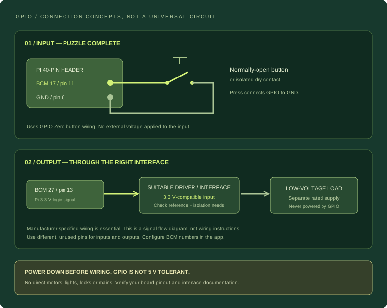
Power up, open Admin > GPIO, and assign BCM 17 to Complete room. Test without a team in the room. Alternatively, before creating saved mappings, add:
GPIO_INPUTS={"complete-room":17}To add a separate monitor-toggle button, use a different free pin, for example BCM 22 / physical pin 15, with its own button to GND:
GPIO_INPUTS={"complete-room":17,"display-toggle":22}Use the second line instead of the first, not as a duplicate environment entry. Saved Admin > GPIO mappings take precedence. Restart after editing /etc/escape-room-screen/environment:
sudo systemctl restart escape-room-screen.serviceMonitor toggle requires supported Pi monitor-control tooling. For reed switches and other puzzle sensors, use only verified dry contacts or a suitable 3.3 V interface — do not assume every sensor is voltage-free.
BEFORE THE FIRST PRESS
A careful final check.
- Match physical pin 1 to your board marking; don’t mirror the map from the underside.
- Use BCM numbers in the app and physical numbers to find the connector positions.
- Check your GPIO mappings, HATs and overlays before selecting an input.
- Power down before connecting wires; use a properly soldered header and secure connectors.
- Keep the 3.3 V and 5 V rails out of dry-contact button wiring.
- Use rated interface hardware and separate load power for outputs. This guide is not a mains, lock or safety-critical wiring design.
Pin assignments cross-checked against Pinout.xyz; button wiring and BCM numbering follow GPIO Zero documentation. Check your exact board’s Raspberry Pi documentation before wiring.
Ready to connect the room?
Keep the map nearby and start with one tested input. Follow the Pi install guide for the application, kiosk display and GPIO configuration.
Configure input events & output triggers in the app ↗
Return to the Pi GPIO setup ↗